Wi-SUN tutorial
This tutorial provides guidelines on how to create your own Wi-SUN Field Area Network (FAN) mesh network and register your devices to Pelion Device Management.
Wi-SUN FAN has been designed for wireless outdoor networks, such as smart metering and street lighting systems. Its performance is optimized for large-scale networks rather than small networks. Therefore, when connecting the devices, be patient; the network formation takes time.
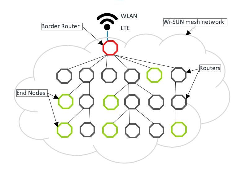 Network topology
Constraints
This Wi-SUN reference deployment is meant for indoor or laboratory environments:
- The reference deployment consists of uncased development boards.
- RF coverage is limited, as the RF shield does not include additional amplifiers.
In RF signaling, the radio EUI64 MAC address must be globally unique, or the devices cannot operate in the same region. You can do this using a separate chip on your own EUI64 range. The Ethernet address (EUI48) must also be unique.
For small-scale testing, use TRNG-randomized EUI64 and EUI48 values. For larger-scale deployments, you must ensure address uniqueness. For more information about obtaining globally unique MAC/Ethernet address see IEEE faqs.
Hardware requirements
To build a Wi-SUN FAN, you need the following devices:
- Wi-SUN devices (for example, 10 pieces).
- RF shields (for each Wi-SUN device and border router).
- A Wi-SUN border router.
-
Ethernet connection (recommended) for the border router, with IPv6 connectivity with stateless address auto configuration (SLAAC) enabled.
-
LTE connection (optionally) for the border router.
- Quectel development board.
- LTE modem.
- SIM card with LTE connection supporting IPv6.
Note: You must ensure you use the correct variant of this modem to work in your country.
-
Reference hardware
Development boards
Several Mbed OS supported boards are available for you to use to evaluate Wi-SUN networks. Some that that are commonly used as reference hardware include:
- Wi-SUN border router or Wi-SUN device.
- Arduino header SPI signals are not connected by default. To connect them, add 0 ohm resistors to R278, R279, R280 and R281 on the backside of the board.
- Arduino header I2C signals D14 and D15 are not capable of master mode. If this mode of I2C is needed, connect D14(SDA) to A4 and D15(SCL) to A5 and select A4 as SDA and A5 as SCL.
- For example, the Atmel RF driver by default uses this I2C to read MAC address from external memory. To disable MAC address read and to use a randomly generated MAC address, add the macro
DISABLE_AT24MACin your build configuration.
- For example, the Atmel RF driver by default uses this I2C to read MAC address from external memory. To disable MAC address read and to use a randomly generated MAC address, add the macro
-
Wi-SUN border router or Wi-SUN device.
Note: You must configure the board to use dual-bank flash layout. The default configuration for F769NI is a single-bank mode. You can use ST-Link utility to change the board to dual-bank mode by enabling the nDBANK byte option. Then, compile the application with
"target.flash_dual_bank": 1enabled. This is the default configuration for Pelion border router.
- Wi-SUN device.
RF shields
- Radio-type in application config:
ATMEL. - Not compatible with Arduino header.
- Connect XPRO Extension header to Arduino header as described in the image.
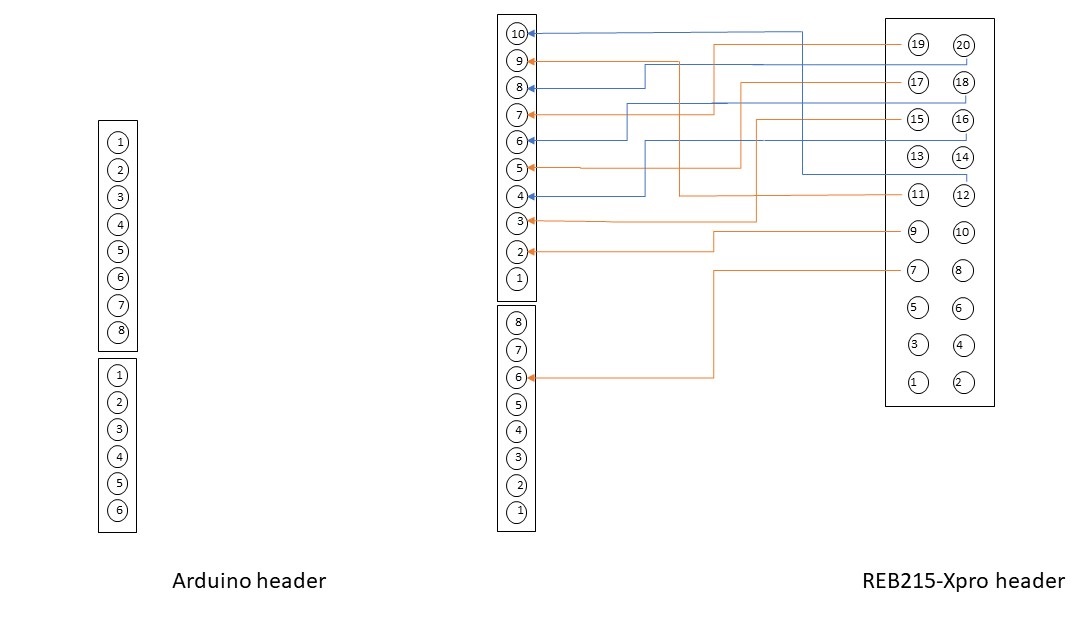 Connecting XPRO to Arduino header
- Radio-type in application config:
S2LP. - The default SPI SCLK pin configuration is D13. On the X-Nucleo-S2868A2, you must solder the resistor R6 instead of R11. For more information, please see the UM2638 user manual.
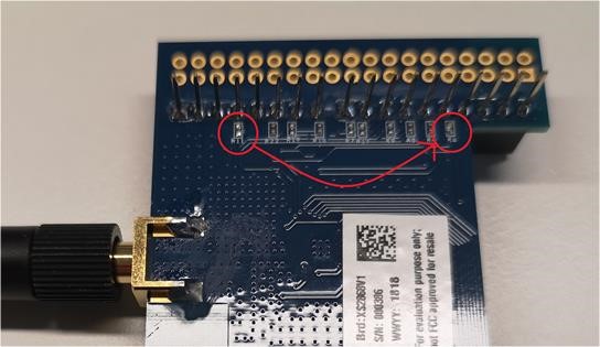 Resistor soldering to R6
Required accounts
You need the following accounts:
Setting up and running the border router
There are two alternative border routers available:
From the mesh network point of view, these border routers are the same. The main difference is Pelion Border Router also contains Device Management Client, which means this border router can register to and use services of Device Management.
To set up the border router:
- Clone the pelion-border-router or nanostack-border-router repository.
- Run
mbed deploy. - Select the target platform.
- Select the toolchain.
- Build with Wi-SUN configurations.
Note: Run mbed detect to list connected targets and supported toolchains.
Pelion Border Router example:
$ mbed deploy

$ mbed target DISCO_F769NI

$ mbed toolchain GCC_ARM

$ mbed compile --app-config mbed_app.json
Nanostack Border Router example:
$ mbed deploy

$ mbed target DISCO_F769NI

$ mbed toolchain GCC_ARM

$ mbed compile --app-config configs/Wisun_Stm_s2lp_RF.json
If you are not using Ethernet with Nanostack Border Router, use configs for LTE backbone instead.
Running the border router application
To run the border router application:
-
Find the binary file
pelion-border-router.binornanostack-border-router.binin theBUILDfolder. -
Copy the binary to the USB mass storage root of the development board. It automatically flashes to the target MCU. When the flashing is complete, the board restarts itself.
-
Press the reset button of the development board if it does not restart automatically.
-
The program begins execution.
-
Open the serial connection, for example with PuTTY.
See more detailed instructions in:
Tip: Use the same Mbed OS version in the border router and the application (Device Management Client).
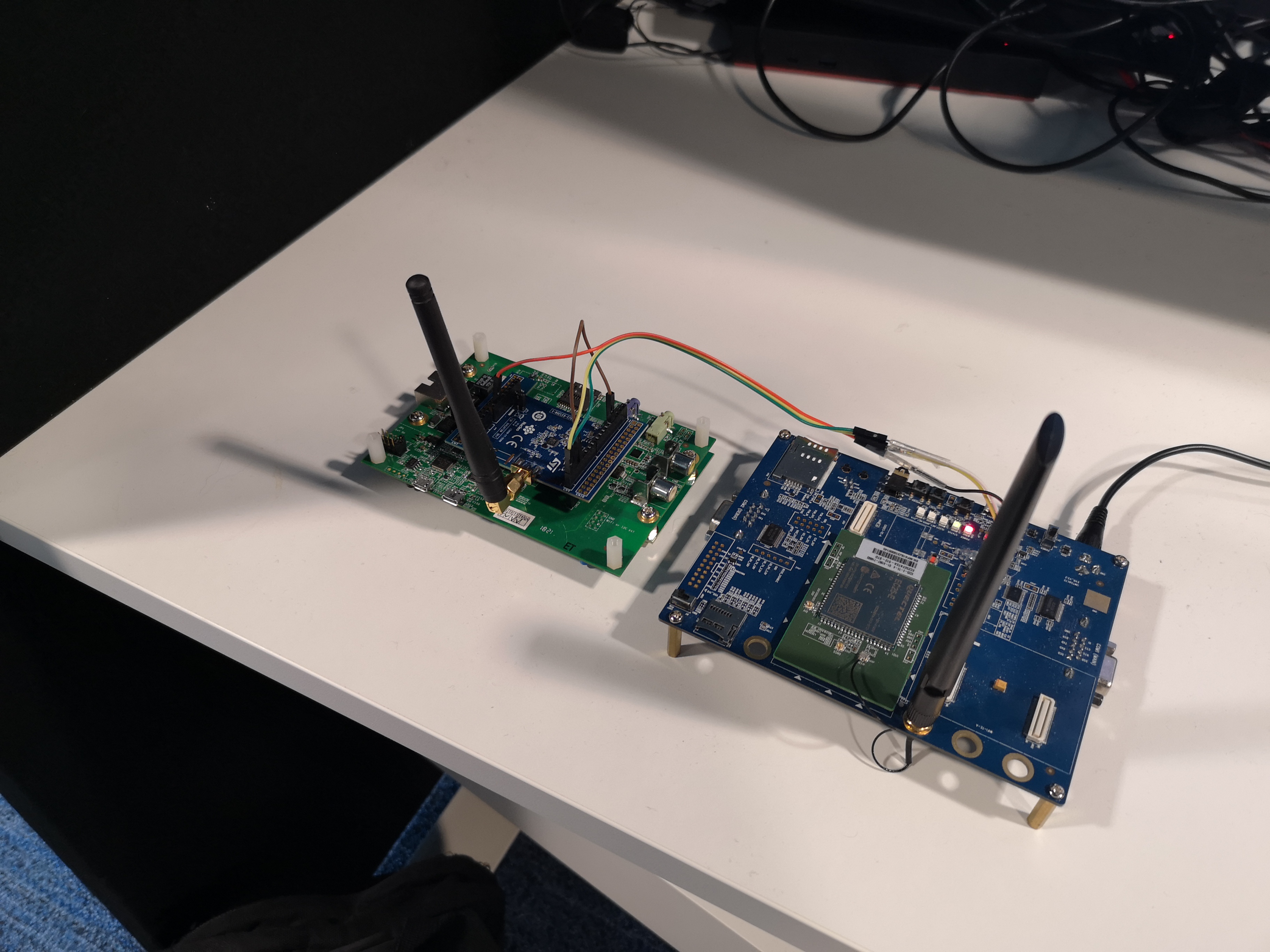 Border router with LTE backbone
Setting up the Wi-SUN devices and connect
Please follow the Pelion Device Management Client tutorial for the prerequisites and basic steps. The key difference is to use the application configuration file for Wi-SUN (configs/mesh_wisun.json) when compiling the client with Nanostack Border Router.
-
If you are using Nanostack Border Router, copy the
configs/mesh_wisun.jsonfile on top of thembed_app.jsonin example root folder. For Pelion Border Router, the filembed_app.jsonalready contains the Wi-SUN configuration settings. -
Use the Wi-SUN certificate definitions file
configs/wisun_certificates.h, or generate your own Wi-SUN certificates (recommended) file to the same location. -
Ensure required Wi-SUN certificates (in file
wisun_certificates.h) are valid (WISUN_ROOT_CERTIFICATE,WISUN_CLIENT_CERTIFICATE,WISUN_CLIENT_KEY), and match the settings you are using with the border router. Invalid certificates or certificates that don't match prevent mesh network formation. -
In the
mbed_cloud_client_user_config.hfile, changeMBED_CLOUD_CLIENT_TRANSPORT_MODE_TCPtoMBED_CLOUD_CLIENT_TRANSPORT_MODE_UDPto use the UDP protocol instead of the default TCP. -
Select the appropriate application startup delay parameters for your network. These parameters help stabilize network formation with more even distribution of client traffic peaks. Specify the parameters in the application configuration file. For a network of 100 connected devices, you could specify for example:
"client_app.startup_min_random_delay" : 100, "client_app.startup_max_random_delay" : 7200, -
Optimize the DNS API configuration to fit for high latency networks. If the client cannot connect to Device Management due to
DnsResolvingFailederrors, we recommend that you fine-tune the Mbed OS DNS API configurations. The Mbed OS defaults are more suitable for low latency networks. For a network of 100 connected devices, specify for example:"nsapi.dns-response-wait-time" : 100000, "nsapi.dns-total-attempts" : 3, "nsapi.dns-retries" : 3,
Tip: Use the same Mbed OS version in the border router and the application (Device Management Client).
Note: When you go to production, please do not use the example Wi-SUN certificate files provided as is due to security reasons.
 Wi-SUN device
Validating
To validate the formation of your Wi-SUN network and the registration of devices to Device Management, open Device Management Portal, and check the devices have been registered:
 Devices in Device Management Portal
Troubleshooting
This is a living list of possible issues and solutions to them.
Additional tools
You can use an Ethernet and RF sniffer to capture traces, then analyze them using Wireshark.
Use a managed switch to capture all traffic through the Ethernet interface. You can configure the switch to mirror all traffic to a single port connected to a computer running Wireshark.
Registration failing
If the device does not register successfully to Pelion Device Management, check the soldering is done properly.
To enable traces, modify the application configuration file:
configs/mesh_wisun_S2LP.jsonif you use Nanostack Border Router.mbed_app.jsonif you use Pelion Border Router`.
"mbed-trace.enable": true
Then ensure you do NOT see this error in the logs:
[ERR ][s2lp]: Failed to change state from 0 to: 30
A Failed to change state error either indicates an antenna circuit failure or a communication issue between the S2-LP transceiver and MCU.
First, check your soldering, and make sure the resistor is properly connected to R6. If you still see the issue, the antenna may not be suitable for use with this configuration.
Problem connecting to Device Management after forming the Wi-SUN network
When the Wi-SUN network has formed but the registration to Device Management is failing, make sure the device has received a routable global address. There should be a NSAPI_STATUS_GLOBAL_UP trace in the logs:
[INFO][plat]: NSAPI_STATUS_GLOBAL_UP
IP: fd00:7283:7e00:0:90af:a769:ada8:9f3c
MAC Address: 92:af:a7:69:ad:a8:9f:3c
If the address of the device is in the form fc00:: or fd00:: it is a Unicast Local Address (ULA) and not globally routable. This can be an indication of the backbone connection from border router not working properly.
In some configurations, where the Wi-SUN network is behind a VPN tunnel or an On Premises deployment, the ULA address is fully functional and there are no issues. Check the address to which the devices are assigned and make sure it matches the deployment type.